The aerosol system is mounted inside a Cessna-172XP. The aerosol inlet is
on the leading wing tip on the starboard side. A temperature and RH sensor is also located on the starboard wing.

Cessna-172XP
Aircraft Aerosol Inlet and T/RH Sensor
The aerosol inlet and T/RH sensor are mounted on the outside of the aircraft.

Aerosol Inlet: The aerosol inlet is mounted on the starboard (right) wing of the aircraft. The aerosol inlet nozzle is a diffuser design with slightly rounded leading edges. The nozzle orifice was sized to be isokinetic for typical C172 airspeeds (~50 m/s) and a volumetric sampling flow rate of 30 LPM. The nozzle and inlet tube are constructed of anodized aluminum. The aerosol inlet passes particles through large diameter flexible conductive tubing to the instrument rack.

T/RH Sensor: The T/RH sensor (Humicap, Vaisala Inc.) is mounted on the outside of the aircraft on the the bottom of the right (starboard) wing. The sensor is mounted inside a counter-flow inlet (on loan from NCAR's ATD group) .
T/RH SENSOR

Counter-flow inlet for sensor (in lab)

Counter-flow inlet for sensor (on wing)

Close-up of counter-flow inlet and sensor
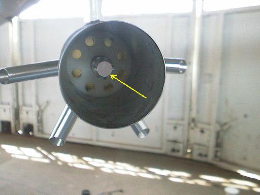
Closer close-up of counter-flow inlet and sensor
AIRCRAFT AEROSOL SYSTEM
The aerosol instrumentation payload is bolted down inside the Cessna. It consists
primarily of a TSI nephelometer
and a Radiance Research particle light
absorption photometer (PSAP). Ancillary equipment includes a 1 micrometer
impactor to exclude supermicrometer particles and a heater to ensure the relative
humidity of the airstream is less than 40% RH.

Front (starboard) view of rack

Back (port) view of rack

View of rack from rear of plane
AIR STREAM CONTROL
The air stream is dried by gentle heating using an in-line heater, and particles
greater than 1 micrometer are removed by an impactor before being sampled by
the light scattering and absorption instruments.

Impactor and heater (in lab) (heater wrapped in yellow tape)
Note: actual configuration on plane is slightly different than this photo

Impactor and heater (on plane) with insulated sample line

Flow control (in lab) - pump, mass flow controller, solonoid valve

Flow control (on plane) - solenoid valve, mass flow controller

